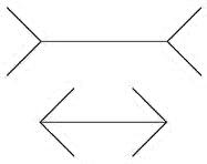
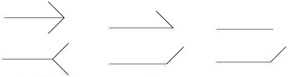
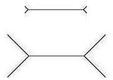
The Müller-Lyer arrow
figure (see the figure on the left below) is the most famous illusion of all, designed in 1889 by
Franz Müller-Lyer. This illusion is created by two lines of equal length, one
line being terminated by outward wings at both ends and another line being
terminated by inward wings at both ends. The line with outward wings appears to
be much longer than the line with inward wings. According to most studies and
my own experiments, the line with outward wings looks about 30% longer than the
line with inward wings to be exact. As shown in the figure on the right below, the two lines look
about the same when the line with outward wings is shortened by 30%.

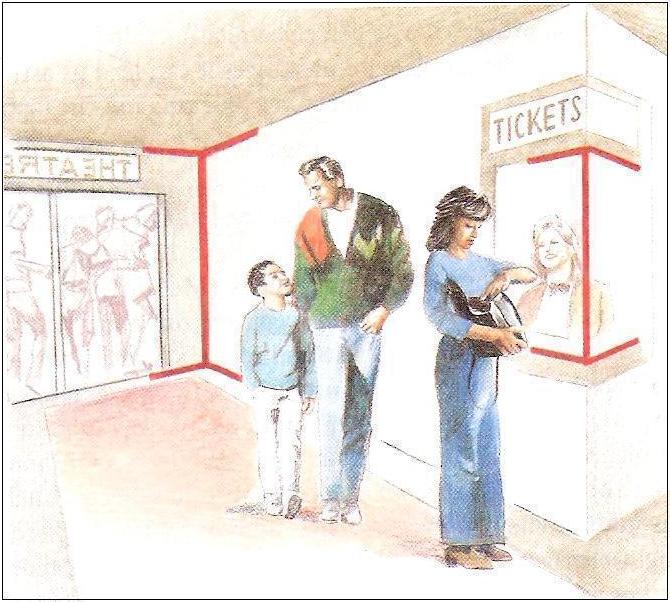
The
often-cited explanation for the Müller-Lyer
illusion was put forth by Richard Gregory (1997). According to his
perspective-constancy theory, the inward and outward facing wings on
either
side of the line segment provide distance cues that cause a viewer to
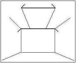
misestimate line length. The picture in the middle above is a
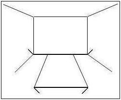
often-illustrated example of the theory. The figure on the right above
can help demonstrate the perspective-constancy theory better, in which
the line segment of the rug in
the front has inward facing wings and it appears closer than the bottom
line
segment of the wall in the back which has outward facing wings.
According to
Gregory, the outward wings make the wall appear further away than the
rug line
segment with inward wings. Based on the fact that the line segments
have the
same length in the figure on the right above and produce the same
retinal image, the length of the
wall in the back is interpreted as being longer than the length of the
rug. Therefore,
the theory states that the Müller-Lyer illusion is consistent with
perspective
cues. (It is also called the Size-distance Invariance Hypothesis, which
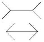
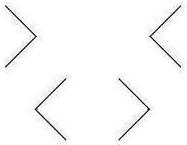
will be discussed later.) However, when we turn the figure around as
shown in the figure on the left below, and the line segment
of the rug is not in the front anymore but on top of the wall, the
illusion still persists. More importantly, the proportion of the
illusion stays
the same as well. In the figure in the middle below, the lines are
taken out, which means that the
images do not give any perspective cues, but these images still induce
the Müller-Lyer
illusion. Furthermore, removing some of the wings, as shown in the
figure on the right, still generates the illusory effect, though to a
lesser degree. But the
figures with fewer than the full wings do not resemble the distance
cues
suggested by Richard Gregory by any stretch of imagination. Therefore,
it can
be concluded that Gregory’s perspective-constancy theory cannot
adequately
explain the Müller-Lyer illusion.
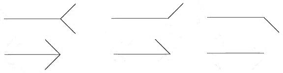
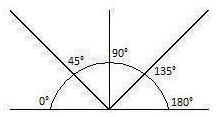
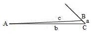
First, we have to choose an angle for both inward and outward wings. Based on my experiments, the illusion effect is diminished extensively when the wing angles are closer to 90°, as shown in the figure on the left below. To control the variations of the illusion magnitude caused by the different angles, I choose 45° angle (∠C) for the inward wings and 135° angle (∠C) for the outward wings, which are the average angles (see the figure in the middle below). In fact, all the wings in the figures of this section are angled as such.
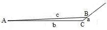
The extra force could be c line in the diagram on the right above which has one outward wing. This line is obviously longer than b line and as such has more force. Hence c line has exerted an effect on our perception of b line and creates an elongated illusion. However, c line has the possibility to connect anywhere on the outward wing. This fact would compromise the 3.75% extension attained earlier because a different connection spot on the wing will generate a line with different length. To settle the issue, I set out to find out on exactly what point of the wing the c line lands. I drew many b lines of different lengths with outward wings at 135° angle. Then I drew a c line with the length of 103.75% of b line. When this was done, I measured a line and found out that the length of a line is approximately 5% of b line without any exception. Now let’s draw the b line with the length of 5cm and then the c line is measured as 5.1875cm in length when the a line is approximately 0.25cm (about 5% of the b line), the difference between b line and c line is:
c - b = 5.1875cm - 5cm = 0.1875cm.
From this result, we know that c line is 3.75% longer than b line after the calculations:
0.1875cm ÷ 5cm = 0.0375cm × 100% = 3.75%.
We can calculate the illusory effect of two, three or four outward wings by simply multiplying the number of wings with 3.75%. As for the inward wings, we should exp
 ect the opposite result because geometry (or
nature) is always symmetrical. As you can see from the diagram on the right, the c line is attached to an inward wing and is obviously shorter than b line; as such the c line in this situation has less force exerted on our perception of b line and creates a shortened
illusion of the b line. Again let b
line be 5cm in length and c line 4.8125cm
in length after setting a line at approximately 5%
of b line. By using the subtraction,
we obtain the following:
ect the opposite result because geometry (or
nature) is always symmetrical. As you can see from the diagram on the right, the c line is attached to an inward wing and is obviously shorter than b line; as such the c line in this situation has less force exerted on our perception of b line and creates a shortened
illusion of the b line. Again let b
line be 5cm in length and c line 4.8125cm
in length after setting a line at approximately 5%
of b line. By using the subtraction,
we obtain the following:
c - b = 4.8125cm - 5cm = -0.1875
If we do the following calculations:
-0.1875cm ÷ 5cm = -0.0375cm × 100% = -3.75%,
It is time to discuss the exception
mentioned earlier regarding the effect of the length of the wings on the
magnitude of the Müller-Lyer illusion. The length of the wings has no obvious
effect on the illusion as shown in the middle figure above except when the length of a wing (a line)
is less than 5% of b line (as shown in the figure on the right above). In this
case the illusory effect is diminished because c line has to connect to the end of a shorter wing. As such, the
shorter the wing, a line, is (only when it is shorter than 5% of b line), the shorter c
line is, then the less effective the Müller-Lyer illusion is. This experiment further proves that the c
line is possibly the influential force of distorting the length of the
shafts. We can also assume that our mind's eye in the visual cortex is
perhaps looking at the diagonal c line, instead of the straight b line. The fact that the length of a line
is approximately 5% of b
line interests me a great deal. Thus, I spent some time looking for an
answer because I believe that this five percent figure has special
meaning or has something to do with the regularity in nature. I will
report my finding in Appendix B.
It turns out that the Müller-Lyer
illusion, especially the finding that a single wing on the shaft can
make its length appear longer or shorter, plays a fundamental role in
all the line distortion illusion caused by diagonal crossing lines.
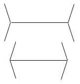
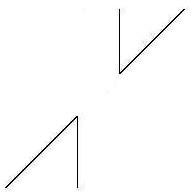
First, we will see how we can explain another famous size illusion, the Poggendorff illusion, using our understanding of the Müller-Lyer illusion.
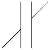


 However, I can successfully explain and
predict the illusion by using the Müller-Lyer
illusion and especially our understanding of the effect of single wing
on the distortion. Now, let's have a close look at the above figure on
the right again, which has two acute angles or inward
wings. As a matter of fact, we can treat each angle as having equal
sides. The vertical line can be seen either as the shaft or as the wing
of the oblique line. Likewise, the oblique line can be seen either as
the shaft or as the wing of the vertical
line. In this case, the vertical line and the oblique line can be
treated as being equivalent. As such, the acute angles in the figure
become ambiguous. The two lines that form the acute angle could be both
shafts or both be wings at the same time. Our visual cortex must be
very confused about this ambiguous situation. It cannot decide whether
it should treat the oblique line as wing or as shaft; similarly, it
cannot figure out what the vertical line should be in this situation, that is, a shaft or a wing. We can assume that the lines forming the
acute angles are so much alike that our cortex simply cannot sort out
which is the shaft and which is the wing. As a result, the oblique line
and the vertical line offset each other, and no misalignment is
perceived. To test my theory of the ambiguous figure of the acute
angles, all we need to do is to change the ambiguous figure into
unambiguous figure. If my theory is correct, the illusion should
re-appear after the ambiguous vertical line is changed into an
unambiguous shaft. To achieve this transformation is simply to extend
the vertical line to make it look like an unambiguous shaft. As shown
in the figure on the left, I have extended the vertical lines. Now I
don't think anybody would doubt that the vertical lines in the left
figure look like anything but a shaft. As predicted, the Müller-Lyer illusion is re-induced and the misalignment of the oblique line has occurred once again. The
positive result of this experiment is a further evidence to support my
approach to the Poggendorff illusion, i.e., the illusion is caused by
the wings of the Müller-Lyer
illusion,
mostly the outward wings because the inward wings in the
standard Poggendorff illusion is ambiguous. The Poggendorff illusion is
a very popular phenomenon for research because it has many interesting
variations. Each unique variation poses new challenge for explaining
the illusion. As such, a satisfactory explanation which can account for
all the variations has been eluding researchers after more than a
hundred years of intensive investigation. No matter whether I have
found the true cause of the Poggendorff illusion or not, the predictive
power of my approach is impressive and very successful.As discussed
later, I can calculate and predict all the variations of the illusion
by using the understand of the Müller-Lyer illusion.
However, I can successfully explain and
predict the illusion by using the Müller-Lyer
illusion and especially our understanding of the effect of single wing
on the distortion. Now, let's have a close look at the above figure on
the right again, which has two acute angles or inward
wings. As a matter of fact, we can treat each angle as having equal
sides. The vertical line can be seen either as the shaft or as the wing
of the oblique line. Likewise, the oblique line can be seen either as
the shaft or as the wing of the vertical
line. In this case, the vertical line and the oblique line can be
treated as being equivalent. As such, the acute angles in the figure
become ambiguous. The two lines that form the acute angle could be both
shafts or both be wings at the same time. Our visual cortex must be
very confused about this ambiguous situation. It cannot decide whether
it should treat the oblique line as wing or as shaft; similarly, it
cannot figure out what the vertical line should be in this situation, that is, a shaft or a wing. We can assume that the lines forming the
acute angles are so much alike that our cortex simply cannot sort out
which is the shaft and which is the wing. As a result, the oblique line
and the vertical line offset each other, and no misalignment is
perceived. To test my theory of the ambiguous figure of the acute
angles, all we need to do is to change the ambiguous figure into
unambiguous figure. If my theory is correct, the illusion should
re-appear after the ambiguous vertical line is changed into an
unambiguous shaft. To achieve this transformation is simply to extend
the vertical line to make it look like an unambiguous shaft. As shown
in the figure on the left, I have extended the vertical lines. Now I
don't think anybody would doubt that the vertical lines in the left
figure look like anything but a shaft. As predicted, the Müller-Lyer illusion is re-induced and the misalignment of the oblique line has occurred once again. The
positive result of this experiment is a further evidence to support my
approach to the Poggendorff illusion, i.e., the illusion is caused by
the wings of the Müller-Lyer
illusion,
mostly the outward wings because the inward wings in the
standard Poggendorff illusion is ambiguous. The Poggendorff illusion is
a very popular phenomenon for research because it has many interesting
variations. Each unique variation poses new challenge for explaining
the illusion. As such, a satisfactory explanation which can account for
all the variations has been eluding researchers after more than a
hundred years of intensive investigation. No matter whether I have
found the true cause of the Poggendorff illusion or not, the predictive
power of my approach is impressive and very successful.As discussed
later, I can calculate and predict all the variations of the illusion
by using the understand of the Müller-Lyer illusion. 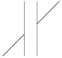 the
lines without wings, the line with outward wing needs to be shortened
by 3.75%. Since there are two outward wings that contribute to the
overall illusion, we have to double the effect. Based on our
understanding of the Müller-Lyer
illusion, we can predict that the alignment of the oblique line is off
7.5%. In other words, the vertical line that helps form the
obtuse angle in the figure look
7.5% longer than the vertical line of the same section without the
wing. If this is the case, to correct the misalignment we should simply
shorten the vertical line with outward wing
or the vertical line that forms the obtuse angle in the figure by 7.5%
to make the oblique line in the figure look aligned. That is what
has exactly happened in the figure on the right when the vertical line
on the right side with outward wing is shortened
by 7.5%. I have experimented with the vertical bars of different
lengths
and widths; and the outcomes are always the same, i.e., the oblique
line
appears aligned when the vertical line with outward wing is shortened
or the vertical line with
inward wing is extended by 7.5%. This explanation of the Poggendorff
illusion reinforces
our understanding of the Müller-Lyer illusion, that is, the
illusion is caused
by a force, the elongated or shortened c line, not by our subjective interpretations. As a result, the predictive power of my approach has been proven again.
the
lines without wings, the line with outward wing needs to be shortened
by 3.75%. Since there are two outward wings that contribute to the
overall illusion, we have to double the effect. Based on our
understanding of the Müller-Lyer
illusion, we can predict that the alignment of the oblique line is off
7.5%. In other words, the vertical line that helps form the
obtuse angle in the figure look
7.5% longer than the vertical line of the same section without the
wing. If this is the case, to correct the misalignment we should simply
shorten the vertical line with outward wing
or the vertical line that forms the obtuse angle in the figure by 7.5%
to make the oblique line in the figure look aligned. That is what
has exactly happened in the figure on the right when the vertical line
on the right side with outward wing is shortened
by 7.5%. I have experimented with the vertical bars of different
lengths
and widths; and the outcomes are always the same, i.e., the oblique
line
appears aligned when the vertical line with outward wing is shortened
or the vertical line with
inward wing is extended by 7.5%. This explanation of the Poggendorff
illusion reinforces
our understanding of the Müller-Lyer illusion, that is, the
illusion is caused
by a force, the elongated or shortened c line, not by our subjective interpretations. As a result, the predictive power of my approach has been proven again. 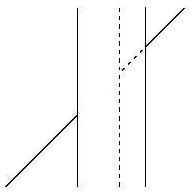 the
expected predictive power. As shown in the figure on the left, the
right side vertical line has been moved from the position of the dotted
line to the solid line position. As you can see, the right solid line
which is the section under the wing or the oblique line is longer than
the same section of the dotted line. Since that section of the vertical
line looks 7.5% longer because of the outward wing attached to it, a
vertical line of 5cm length with the outward wing would look as long as
5.375cm in comparison to a vertical line of the same length without the
wing. If we let that section of the solid right vertical line be
increased to 6cm, the section of the solid line under the wing would
look 6.45cm in length in contrast to a 6cm vertical line without the
wing. To reduce that section of the vertical line to make the oblique
line appear to be aligned, the 5cm vertical line has to be reduced by
7.5% to 4.625cm to make the oblique line look aligned. On the other
hand, the 6cm section of the newly widened vertical line has to be
shortened to 5.55cm to make the oblique line appear aligned. The longer
vertical line section has to be shortened by 0.45cm versus 0.375cm for the shorter dotted vertical line section in the
figure if we assume the solid line section is 6cm and the dotted line
section is 5cm. The longer solid line section has to be reduced 20%
more than the shorter dotted line section to make the oblique line
appear aligned. Accordingly, the longer the vertical line section under
the outward wing is, the more misaligned the oblique line appears to be
in the Poggendorff illusion. Since the wider the vertical bar, the
longer the vertical line section under the outward wing, therefore the
wider vertical bar makes the illusory effect more distorted and
perceptible.
the
expected predictive power. As shown in the figure on the left, the
right side vertical line has been moved from the position of the dotted
line to the solid line position. As you can see, the right solid line
which is the section under the wing or the oblique line is longer than
the same section of the dotted line. Since that section of the vertical
line looks 7.5% longer because of the outward wing attached to it, a
vertical line of 5cm length with the outward wing would look as long as
5.375cm in comparison to a vertical line of the same length without the
wing. If we let that section of the solid right vertical line be
increased to 6cm, the section of the solid line under the wing would
look 6.45cm in length in contrast to a 6cm vertical line without the
wing. To reduce that section of the vertical line to make the oblique
line appear to be aligned, the 5cm vertical line has to be reduced by
7.5% to 4.625cm to make the oblique line look aligned. On the other
hand, the 6cm section of the newly widened vertical line has to be
shortened to 5.55cm to make the oblique line appear aligned. The longer
vertical line section has to be shortened by 0.45cm versus 0.375cm for the shorter dotted vertical line section in the
figure if we assume the solid line section is 6cm and the dotted line
section is 5cm. The longer solid line section has to be reduced 20%
more than the shorter dotted line section to make the oblique line
appear aligned. Accordingly, the longer the vertical line section under
the outward wing is, the more misaligned the oblique line appears to be
in the Poggendorff illusion. Since the wider the vertical bar, the
longer the vertical line section under the outward wing, therefore the
wider vertical bar makes the illusory effect more distorted and
perceptible. 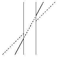 cannot adequately account for this
phenomenon would be deemed incomplete. My
approach to explaining this phenomenon is very similar to that of
widening vertical bar above. Actually, there is a great similarity
between these two variations of the illusion. As you can see in the
figure on the right, when you rotate the oblique line from the dotted
position counterclockwise to the solid line position, the right side vertical line below the oblique line has lengthened. As such, we
can use exactly the same logic that we used earlier for the widening of
the vertical bar to explain the effect of the tilting oblique line on
the increased illusion. (To save the space, I am going to forgo the
calculations.) Since the
longer right
vertical line section below the solid oblique line, as illustrated in
the figure on the right, has to be reduced more than the shorter
vertical line section below the dotted oblique line to make the solid
oblique line
appear aligned. Accordingly, the longer the vertical line section below
the oblique line or outward wing is, the more misaligned the oblique
line appears to be
in the Poggendorff illusion. For the more tilted the oblique line, the
longer the vertical line section below the outward wing, therefore the
more tilted oblique line makes the illusory effect more obvious and
salient.
cannot adequately account for this
phenomenon would be deemed incomplete. My
approach to explaining this phenomenon is very similar to that of
widening vertical bar above. Actually, there is a great similarity
between these two variations of the illusion. As you can see in the
figure on the right, when you rotate the oblique line from the dotted
position counterclockwise to the solid line position, the right side vertical line below the oblique line has lengthened. As such, we
can use exactly the same logic that we used earlier for the widening of
the vertical bar to explain the effect of the tilting oblique line on
the increased illusion. (To save the space, I am going to forgo the
calculations.) Since the
longer right
vertical line section below the solid oblique line, as illustrated in
the figure on the right, has to be reduced more than the shorter
vertical line section below the dotted oblique line to make the solid
oblique line
appear aligned. Accordingly, the longer the vertical line section below
the oblique line or outward wing is, the more misaligned the oblique
line appears to be
in the Poggendorff illusion. For the more tilted the oblique line, the
longer the vertical line section below the outward wing, therefore the
more tilted oblique line makes the illusory effect more obvious and
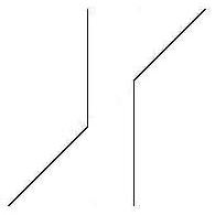
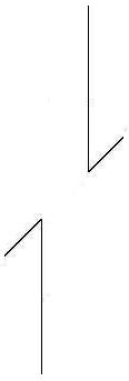
salient. 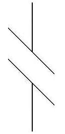 A popular explanation for the Poggendorff illusion is a so-called depth-processing theory. I
don't want to spend time and space to go into details about this theory
(if you are interested in the theory, check out this site.) since it can be dismissed due
to a fatal flaw of the theory, which is that it cannot account for the
observation that when the standard Poggendorff figure is tilted so that
the interrupted oblique lines are set vertically at 90º or
horizontally at 180º, the illusory misalignment effect weakens or
disappears. (The figure on the left shows the standard Poggendorff figure is tilted vertically at 90º.) Merely
tilting the figure should not change any presumed perspective features
of the figure. Thus, the depth-processing theory is flawed. However,
using the winged force found in the Müller-Lyer
illusion
I can adequately explain this delinquency of the standard Poggendorff
illusion. When the vertical bar is tilted, the former vertical lines
have now become the oblique lines in the figure, and the former oblique
line has become the straight vertical line which is the shaft instead
of the previous wings, as shown in the figure on the left. Now, the
shaft or the vertical line, no matter whether it is above the tilted
obscuring bar or under, has both an inward wing and an outward wing
attached to its end. Since the wings only affect the shaft to make them
either appear longer or shorter, a longer or shorter shafts will not be
misaligned with each other because the wi
A popular explanation for the Poggendorff illusion is a so-called depth-processing theory. I
don't want to spend time and space to go into details about this theory
(if you are interested in the theory, check out this site.) since it can be dismissed due
to a fatal flaw of the theory, which is that it cannot account for the
observation that when the standard Poggendorff figure is tilted so that
the interrupted oblique lines are set vertically at 90º or
horizontally at 180º, the illusory misalignment effect weakens or
disappears. (The figure on the left shows the standard Poggendorff figure is tilted vertically at 90º.) Merely
tilting the figure should not change any presumed perspective features
of the figure. Thus, the depth-processing theory is flawed. However,
using the winged force found in the Müller-Lyer
illusion
I can adequately explain this delinquency of the standard Poggendorff
illusion. When the vertical bar is tilted, the former vertical lines
have now become the oblique lines in the figure, and the former oblique
line has become the straight vertical line which is the shaft instead
of the previous wings, as shown in the figure on the left. Now, the
shaft or the vertical line, no matter whether it is above the tilted
obscuring bar or under, has both an inward wing and an outward wing
attached to its end. Since the wings only affect the shaft to make them
either appear longer or shorter, a longer or shorter shafts will not be
misaligned with each other because the wi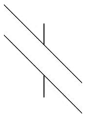 ngs
only affect the shafts vertically in the figure on the left. As a
result, the vertical lines in the figure on the left do not look
displaced from each other and the illusory effect of the Poggendorff
illusion has been severely weakened if not totally eliminated. However,
those researchers who found the variant of the Poggendorff illusion in
the figure on the left did not realize that the same variant could have
its own variant as well. As shown in the figure on the right, the
ninety degree tilted standard Poggendorff illusion figure is now again
misaligned for the vertical lines. How come the tilted Poggendorff figure
on the left has weakened vertical line misalgnment and the same tilted
Poggendorff figure on the right has the illusory vertical line
misalignment? For those who don't have the knowledge of the winged force found in the Müller-Lyer
illusion discussed earlier, it is hard to comprehend why the same figure can have two different perceptual effects. Whether
the vertical lines in the figure is misaligned or not depends on the
length of the vertical lines relative to the oblique lines. If the
vertical line is longer than the left side and right side of the
oblique line, the vertical lines are not misaligned in the figure
because the vertical lines are treated by our visual cortex as the
shafts and the oblique lines as the inward or outward wings; therefore,
as explained earlier, the
wings only affect the shaft to make them either appear longer or
shorter, a longer or shorter shafts will not be misaligned with each
other. On
the other hand, in the figure on the right the vertical lines are
shorter than the either side of the oblique lines; thus the vertical
lines in the figure are not treated by our cortex as the shafts but as
the wings attached to the oblique lines. The
effect of this arrangement would be similar to the standard Poggendorff
illusion figure in which the oblique line sections attached to the
outward wings, which are the vertical lines now, are elongated. As
such, the upper vertical line in the figure on the right looks
misaligned from the lower vertical line. These experiments further
prove the explanatory and predictive power of the winged force found in
the Müller-Lyer
illusion.
ngs
only affect the shafts vertically in the figure on the left. As a
result, the vertical lines in the figure on the left do not look
displaced from each other and the illusory effect of the Poggendorff
illusion has been severely weakened if not totally eliminated. However,
those researchers who found the variant of the Poggendorff illusion in
the figure on the left did not realize that the same variant could have
its own variant as well. As shown in the figure on the right, the
ninety degree tilted standard Poggendorff illusion figure is now again
misaligned for the vertical lines. How come the tilted Poggendorff figure
on the left has weakened vertical line misalgnment and the same tilted
Poggendorff figure on the right has the illusory vertical line
misalignment? For those who don't have the knowledge of the winged force found in the Müller-Lyer
illusion discussed earlier, it is hard to comprehend why the same figure can have two different perceptual effects. Whether
the vertical lines in the figure is misaligned or not depends on the
length of the vertical lines relative to the oblique lines. If the
vertical line is longer than the left side and right side of the
oblique line, the vertical lines are not misaligned in the figure
because the vertical lines are treated by our visual cortex as the
shafts and the oblique lines as the inward or outward wings; therefore,
as explained earlier, the
wings only affect the shaft to make them either appear longer or
shorter, a longer or shorter shafts will not be misaligned with each
other. On
the other hand, in the figure on the right the vertical lines are
shorter than the either side of the oblique lines; thus the vertical
lines in the figure are not treated by our cortex as the shafts but as
the wings attached to the oblique lines. The
effect of this arrangement would be similar to the standard Poggendorff
illusion figure in which the oblique line sections attached to the
outward wings, which are the vertical lines now, are elongated. As
such, the upper vertical line in the figure on the right looks
misaligned from the lower vertical line. These experiments further
prove the explanatory and predictive power of the winged force found in
the Müller-Lyer
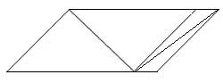
illusion. 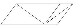 e within the larger left-side sub-parallelogram appears to be considerably longer
than the diagonal line within the smaller right-side sub-parallelogram. This simple illusion has been evading and frustrating researchers for many years. The best explanation they can come up with is that the sub-parallelograms around the bisecting lines perhaps give a perception of
depth, and when the bisecting lines are included in that depth, they
are perceived as different lengths.
This is basically just a wild guess and nobody knows how this
perception of depth actually works. However, the illusion can be
easily explained based on the understanding of the mechanism of
the Müller-Lyer illusion; and the magnitude of the illusory effect can be predicted and corrected. be
easily ignored. If we ignore the dotted lines in the figure on the left
below and focus our attention only on the solid lines, we will see a
familiar figure, which is almost the same as the figure of a shaft
being connected by four inward wings at its ends in the Müller-Lyer
illusion
which is shown as the lower figure in the diagram on the right. The
figure on the right below is the enlarged image of the larger left-side
sub-parallelogram in the Sander illusion. The dotted lines in the
diagram help to show the shape of the sub-parallelogram and can be
easily ignored. The top of the diagonal line is connected to an inward
wing on the right side and a ninety degree wing on the left side which
has no illusory effect on the shaft. The bottom of the diagonal line is
a little bit more complicated. It is connected to an inward wing on its
left and connected to three wings on its right. Out of these three
wings, one is ninety degree wing which has no illusory effect on the
diagonal line and can be ignored. The remaining two wings are both
outward wings. These two outward wings on the same side of the diagonal
line would have the same effect on the shaft. Thus, I have dotted one
line and left the line which I think is more likely to be chosen
by our brain as the influential outward wing solid. If
we ignore the dotted lines in the right figure below, we will see a
shaft being connected to a ninety degree wing, two inward wings, and an
outward wing.
e within the larger left-side sub-parallelogram appears to be considerably longer
than the diagonal line within the smaller right-side sub-parallelogram. This simple illusion has been evading and frustrating researchers for many years. The best explanation they can come up with is that the sub-parallelograms around the bisecting lines perhaps give a perception of
depth, and when the bisecting lines are included in that depth, they
are perceived as different lengths.
This is basically just a wild guess and nobody knows how this
perception of depth actually works. However, the illusion can be
easily explained based on the understanding of the mechanism of
the Müller-Lyer illusion; and the magnitude of the illusory effect can be predicted and corrected. be
easily ignored. If we ignore the dotted lines in the figure on the left
below and focus our attention only on the solid lines, we will see a
familiar figure, which is almost the same as the figure of a shaft
being connected by four inward wings at its ends in the Müller-Lyer
illusion
which is shown as the lower figure in the diagram on the right. The
figure on the right below is the enlarged image of the larger left-side
sub-parallelogram in the Sander illusion. The dotted lines in the
diagram help to show the shape of the sub-parallelogram and can be
easily ignored. The top of the diagonal line is connected to an inward
wing on the right side and a ninety degree wing on the left side which
has no illusory effect on the shaft. The bottom of the diagonal line is
a little bit more complicated. It is connected to an inward wing on its
left and connected to three wings on its right. Out of these three
wings, one is ninety degree wing which has no illusory effect on the
diagonal line and can be ignored. The remaining two wings are both
outward wings. These two outward wings on the same side of the diagonal
line would have the same effect on the shaft. Thus, I have dotted one
line and left the line which I think is more likely to be chosen
by our brain as the influential outward wing solid. If
we ignore the dotted lines in the right figure below, we will see a
shaft being connected to a ninety degree wing, two inward wings, and an
outward wing. 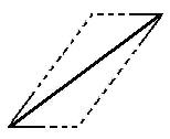
 should appear 3.75% shorter than a line of the same
length based on the calculation: (-3.75% × 2) + 3.75% = -3.75%. The difference between
the two diagonal lines is: (-15%) – (-3.75%) = -11.25%. Accordingly,
the diagonal line in the right-side sub-parallelogram appears 11.25%
shorter than the diagonal
line in the left-side sub-parallelogram. If our understanding of the
illusion and calculations are correct, the two diagonal lines should
look the
same length when the left-side diagonal line is shortened by 11.25%. As
shown
in the figure on the left, the two diagonal lines appear to be the same
length when the left-side diagonal line is actually 11.25% shorter than
the right-side diagonal line. This result demonstrates that the mechanism of the Müller-Lyer illusion can be used to explain and calculate any line
illusion caused by the wings attached to its ends. The predictive power of the winged force in the Müller-Lyer illusion has been proven once again.
should appear 3.75% shorter than a line of the same
length based on the calculation: (-3.75% × 2) + 3.75% = -3.75%. The difference between
the two diagonal lines is: (-15%) – (-3.75%) = -11.25%. Accordingly,
the diagonal line in the right-side sub-parallelogram appears 11.25%
shorter than the diagonal
line in the left-side sub-parallelogram. If our understanding of the
illusion and calculations are correct, the two diagonal lines should
look the
same length when the left-side diagonal line is shortened by 11.25%. As
shown
in the figure on the left, the two diagonal lines appear to be the same
length when the left-side diagonal line is actually 11.25% shorter than
the right-side diagonal line. This result demonstrates that the mechanism of the Müller-Lyer illusion can be used to explain and calculate any line
illusion caused by the wings attached to its ends. The predictive power of the winged force in the Müller-Lyer illusion has been proven once again. 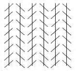 left, can be
explained based on the understanding of the mechanism of the Müller-Lyer illusion. As a matter of fact, the understanding of the Zöllner illusion based on the mechanism of the Müller-Lyer illusion has become the key to opening all the puzzles of the size or shape illusions caused by a tilting crossing line over a straight or curved line. The illusory effect for the Zöllner
illusion
is that the vertical lines in the figure are actually parallel to each
other, but appear to tilt. There are numerous attempts to explain this
illusion. The most popular and acceptable explanation is that in the Zollner illusion, the shorter lines are on an angle to the longer
lines. This angle helps to create the impression that one end of the longer
lines is nearer to us than the other end; and it may be that the Zollner illusion is caused by this
impression of depth. Another suggested way to look at the illusion is that the brain tries to increase the
angle between the long line and the shorter lines that cross it; as a result,
the brain bends the longer lines towards or away from each other. In comparison, the advantage of my explanation of the illusion is that we can use the same understanding of the Zöllner illusion to predict and explain all the other size or shape illusions caused by a tilting crossing line over a straight or curved line.
left, can be
explained based on the understanding of the mechanism of the Müller-Lyer illusion. As a matter of fact, the understanding of the Zöllner illusion based on the mechanism of the Müller-Lyer illusion has become the key to opening all the puzzles of the size or shape illusions caused by a tilting crossing line over a straight or curved line. The illusory effect for the Zöllner
illusion
is that the vertical lines in the figure are actually parallel to each
other, but appear to tilt. There are numerous attempts to explain this
illusion. The most popular and acceptable explanation is that in the Zollner illusion, the shorter lines are on an angle to the longer
lines. This angle helps to create the impression that one end of the longer
lines is nearer to us than the other end; and it may be that the Zollner illusion is caused by this
impression of depth. Another suggested way to look at the illusion is that the brain tries to increase the
angle between the long line and the shorter lines that cross it; as a result,
the brain bends the longer lines towards or away from each other. In comparison, the advantage of my explanation of the illusion is that we can use the same understanding of the Zöllner illusion to predict and explain all the other size or shape illusions caused by a tilting crossing line over a straight or curved line. 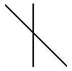 the standard Zöllner illusion figure, representing a single diagonal line crossing the vertical line. It is the top right corner of the Zöllner illusion figure with a diagonal
line going downwards from left to right across a vertical line. As we look at the figure closely, we should
notice the similarity between the figure on the right and the Müller-Lyer illusion, especially the
figure on the left. First we will analyze the top half of the figure which is above the
diagonal line, as shown in the figure on the left below. When we look
at the figure on the left below, let's ignore the dotted line and focus
on the solid lines only. The diagonal line on
the left-side of the vertical line can be regarded as the inward wing
of the solid vertical line, and the diagonal
line on the right-side of the vertical line can be treated as the
outward wing of the solid vertical line. The only difference between the figure on the left which is the Müller-Lyer illusion and the figure on the left below is that in the figure on the left below the two
wings are
sharing the same vertical line or the shaft and in the figure on the
left they do not share the same shaft. Because of
the fact that the inward and outward wings share the same shaft, the
winged forces on both sides of the shared shaft are unequal, resulting
in two different forces working on both sides of the vertical line and
pulling on the shared vertical
line.
The force on the left side of the top half vertical line is 3.75% less
than the vertical line because the left wing is an inward wing which
has an invisible line (the c line in the middle diagram below) 3.75% shorter than the shaft (the b line);
and the force
on the right side of the top half vertical line is 3.75% more than the
vertical line because the right wing is an outward wing which has an
invisible line (the c line in the diagram on the right below) 3.75% longer than the shaft (the b line).
As a consequence, the right
side of the top half vertical line has 7.5% more force than the left
side because the positive force on the right side minus the negative
force on the left side and we get: 3.75% - (-3.75%) = 7.5%. If you are still unclear on these forces working on the vertical line, try to visualize
this scenario: A telephone pole with two ropes fastened
to it is pulled by people on opposite sides of the pole. Let's assume
that the strength of the pole is equal to the force of 100 people. One
side of the pole has 3.75% less people than 100; thus we have 96 people on this side of the pole pulling on the pole. On the other hand, the other side has 3.75% more people than
100; thus we have 103.5 people on the opposite side of the pole pulling
on the rope. As a consequence, one side has about 7.5% more people than
the other side pulling on the rope; and obviously the pole will tilt
toward the side with
more people pulling on it if all the people involved have equal
strength. This
is exactly what has happened to the top half of the vertical line in
the
figure on the right, which tends to tilt toward the right, which is the
side with the outward wing that has 7.5%
more strength than the side with the inward wing.
the standard Zöllner illusion figure, representing a single diagonal line crossing the vertical line. It is the top right corner of the Zöllner illusion figure with a diagonal
line going downwards from left to right across a vertical line. As we look at the figure closely, we should
notice the similarity between the figure on the right and the Müller-Lyer illusion, especially the
figure on the left. First we will analyze the top half of the figure which is above the
diagonal line, as shown in the figure on the left below. When we look
at the figure on the left below, let's ignore the dotted line and focus
on the solid lines only. The diagonal line on
the left-side of the vertical line can be regarded as the inward wing
of the solid vertical line, and the diagonal
line on the right-side of the vertical line can be treated as the
outward wing of the solid vertical line. The only difference between the figure on the left which is the Müller-Lyer illusion and the figure on the left below is that in the figure on the left below the two
wings are
sharing the same vertical line or the shaft and in the figure on the
left they do not share the same shaft. Because of
the fact that the inward and outward wings share the same shaft, the
winged forces on both sides of the shared shaft are unequal, resulting
in two different forces working on both sides of the vertical line and
pulling on the shared vertical
line.
The force on the left side of the top half vertical line is 3.75% less
than the vertical line because the left wing is an inward wing which
has an invisible line (the c line in the middle diagram below) 3.75% shorter than the shaft (the b line);
and the force
on the right side of the top half vertical line is 3.75% more than the
vertical line because the right wing is an outward wing which has an
invisible line (the c line in the diagram on the right below) 3.75% longer than the shaft (the b line).
As a consequence, the right
side of the top half vertical line has 7.5% more force than the left
side because the positive force on the right side minus the negative
force on the left side and we get: 3.75% - (-3.75%) = 7.5%. If you are still unclear on these forces working on the vertical line, try to visualize
this scenario: A telephone pole with two ropes fastened
to it is pulled by people on opposite sides of the pole. Let's assume
that the strength of the pole is equal to the force of 100 people. One
side of the pole has 3.75% less people than 100; thus we have 96 people on this side of the pole pulling on the pole. On the other hand, the other side has 3.75% more people than
100; thus we have 103.5 people on the opposite side of the pole pulling
on the rope. As a consequence, one side has about 7.5% more people than
the other side pulling on the rope; and obviously the pole will tilt
toward the side with
more people pulling on it if all the people involved have equal
strength. This
is exactly what has happened to the top half of the vertical line in
the
figure on the right, which tends to tilt toward the right, which is the
side with the outward wing that has 7.5%
more strength than the side with the inward wing. 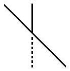 the right
side of the vertical line is the inward wing. As a result, the bottom half of the line tilts toward the
the right
side of the vertical line is the inward wing. As a result, the bottom half of the line tilts toward the 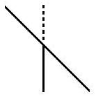 left, which is the side with the outward wing because the left
side of the bottom half vertical line has 7.5% more force than the left side of the vertical line. However, the vertical line as a whole tilts or
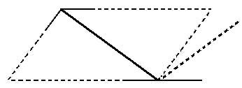
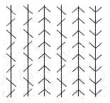
rotates in the same direction, which is clockwise. When all the diagonal lines slant the
same way on a vertical line as in the Zöllner illusion, the vertical
line
will tilt consistently toward the side where the outward wings
are located. If all the diagonal lines on a vertical line slant from
left downward to right, the whole vertical line will rotate clockwise;
if all the diagonal lines on a vertical line slant from right downward
to left, the whole vertical line will rotate counterclockwise, as shown
in the figure on the left, which is the standard Sander illusion.
left, which is the side with the outward wing because the left
side of the bottom half vertical line has 7.5% more force than the left side of the vertical line. However, the vertical line as a whole tilts or
rotates in the same direction, which is clockwise. When all the diagonal lines slant the
same way on a vertical line as in the Zöllner illusion, the vertical
line
will tilt consistently toward the side where the outward wings
are located. If all the diagonal lines on a vertical line slant from
left downward to right, the whole vertical line will rotate clockwise;
if all the diagonal lines on a vertical line slant from right downward
to left, the whole vertical line will rotate counterclockwise, as shown
in the figure on the left, which is the standard Sander illusion. 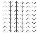
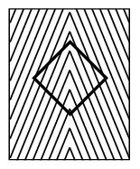
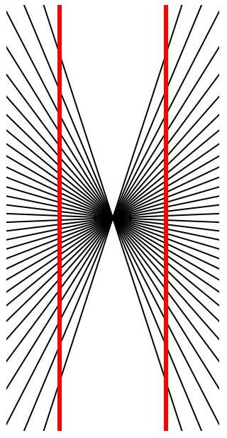 both straight, but they look as if they were
bowing outwards. The generally accepted explanation is that the distortion is produced by the
both straight, but they look as if they were
bowing outwards. The generally accepted explanation is that the distortion is produced by the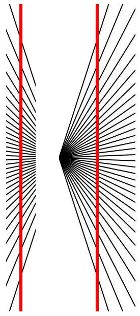 lined pattern on the
background, that simulates a perspective design, and creates a false impression
of depth. Specifically, the illusion figure on the left looks like bike spokes around a central point, with
vertical lines on either side of this central, so-called vanishing point. The
illusion tricks us into thinking we are moving forward. Since we aren't actually
moving and the figure is static, we misperceive the straight lines as curved
ones. I am not going to critique this explanation, but simply use the principle above to analyze the illusion. I
let the readers decide which explanation is more possible and
acceptable. But I need to remind you that it is almost impossible to
determine the true cause of these illusions; all we can hope for is to
find regularities of the illusions and have a better prediction of
their happenings. Again, the principle is: If
all the diagonal lines on a vertical line slant from left downward
to right, the whole vertical line will rotate clockwise; if all the
diagonal lines on a vertical line slant from right downward to left, the whole vertical line will rotate counterclockwise.
lined pattern on the
background, that simulates a perspective design, and creates a false impression
of depth. Specifically, the illusion figure on the left looks like bike spokes around a central point, with
vertical lines on either side of this central, so-called vanishing point. The
illusion tricks us into thinking we are moving forward. Since we aren't actually
moving and the figure is static, we misperceive the straight lines as curved
ones. I am not going to critique this explanation, but simply use the principle above to analyze the illusion. I
let the readers decide which explanation is more possible and
acceptable. But I need to remind you that it is almost impossible to
determine the true cause of these illusions; all we can hope for is to
find regularities of the illusions and have a better prediction of
their happenings. Again, the principle is: If
all the diagonal lines on a vertical line slant from left downward
to right, the whole vertical line will rotate clockwise; if all the
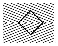
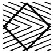
diagonal lines on a vertical line slant from right downward to left, the whole vertical line will rotate counterclockwise.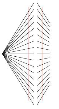 the figure on
  the left, produces a similar, but inverted effect of the Hering illusion. The distorted appearance of the two parallel red lines is created by the
angled lines in the background. The exact mechanism by which we perceive the
illusion is claimed to be not fully understood by the perception researchers, but it is speculated that the illusion might have something to do with the
way the brain and visual system perceive
the angles that surround the two red lines; and it might be
enhanced by the impression of depth created by linear perspective. Put
this explanation aside, let's use the principle to analyze the Wundt
illusion. I have turned the standard Wundt illusion figure by ninety degrees to resemble the Zöllner
illusion figure. If we pay attention only on the right
side vertical line and its
crossing diagonal lines as shown in the figure on the right in which
the diagonal lines are shortened, we see a figure which is exactly the
same as the figure on the right above. Now we can use the same way that we have analyzed the Hering illusion earlier to dissect the figure on the right. The vertical line and its crossing diagonal lines can be
seen as two Zöllner
illusion line sections with
a
horizontal line crossing it in the very middle. This horizontal line is
the dividing line, above which all the diagonal lines slant from
left downward to right and below which all the diagonal lines slant
from right downward to left. Accordingly, the
top half section of the vertical line rotates clockwise; and the bottom
half section of the vertical line rotates counterclockwise. The
left vertical line in the figure on the right has the opposite
condition.
the left, produces a similar, but inverted effect of the Hering illusion. The distorted appearance of the two parallel red lines is created by the
angled lines in the background. The exact mechanism by which we perceive the
illusion is claimed to be not fully understood by the perception researchers, but it is speculated that the illusion might have something to do with the
way the brain and visual system perceive
the angles that surround the two red lines; and it might be
enhanced by the impression of depth created by linear perspective. Put
this explanation aside, let's use the principle to analyze the Wundt
illusion. I have turned the standard Wundt illusion figure by ninety degrees to resemble the Zöllner
illusion figure. If we pay attention only on the right
side vertical line and its
crossing diagonal lines as shown in the figure on the right in which
the diagonal lines are shortened, we see a figure which is exactly the
same as the figure on the right above. Now we can use the same way that we have analyzed the Hering illusion earlier to dissect the figure on the right. The vertical line and its crossing diagonal lines can be
seen as two Zöllner
illusion line sections with
a
horizontal line crossing it in the very middle. This horizontal line is
the dividing line, above which all the diagonal lines slant from
left downward to right and below which all the diagonal lines slant
from right downward to left. Accordingly, the
top half section of the vertical line rotates clockwise; and the bottom
half section of the vertical line rotates counterclockwise. The
left vertical line in the figure on the right has the opposite
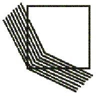
condition.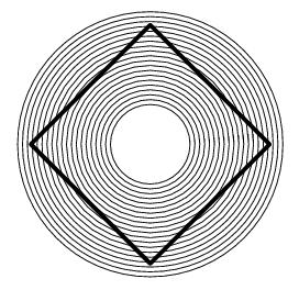 curved
shape, however the square is perfect with perfectly straight sides. So
far there is no generally acceptable explanation for the illusion.
Some people suggest that the circle as a whole acts like a lens,
probably a concave lens, so that when we look at the square through this lens, the square looks distorted. Whoever came up with this explanation has a
curved
shape, however the square is perfect with perfectly straight sides. So
far there is no generally acceptable explanation for the illusion.
Some people suggest that the circle as a whole acts like a lens,
probably a concave lens, so that when we look at the square through this lens, the square looks distorted. Whoever came up with this explanation has a  very good imagination but has no regard for scientific rigorousness. Nevertheless, we can turn a part of the illusion into a Zöllner
illusion
figure and use the same principle to analyze it. As shown in the figure
on the right, I have isolated one side of the square from the rest of
the square. If we ignore the rest of the square and concentrate only on
the isolated line and the diagonal lines crossing it, we will find that
it is similar to the isolated lines for the Hering illusion and the
Wundt illusion discussed above. (By the way, I have failed to turn the
figure around so that the square would sit squarely in the circle and
would have two vertical lines and two horizontal lines. Now, you have
to tilt your head slightly to the right and regard the isolated line as
a vertical line.) Again, the vertical
line (as you look at it when tilting your head to the right) and its
crossing diagonal lines, even though they are not straight and slightly
curved, can be viewed as two Zöllner
illusion line sections. The
top
half section of the vertical line rotates clockwise because all the
diagonal lines slant from left downward to right; and the bottom
half section of the vertical line rotates counterclockwise because all the diagonal lines slant
from right downward to left. Hence, the line is curved this way, so do other three sides.
very good imagination but has no regard for scientific rigorousness. Nevertheless, we can turn a part of the illusion into a Zöllner
illusion
figure and use the same principle to analyze it. As shown in the figure
on the right, I have isolated one side of the square from the rest of
the square. If we ignore the rest of the square and concentrate only on
the isolated line and the diagonal lines crossing it, we will find that
it is similar to the isolated lines for the Hering illusion and the
Wundt illusion discussed above. (By the way, I have failed to turn the
figure around so that the square would sit squarely in the circle and
would have two vertical lines and two horizontal lines. Now, you have
to tilt your head slightly to the right and regard the isolated line as
a vertical line.) Again, the vertical
line (as you look at it when tilting your head to the right) and its
crossing diagonal lines, even though they are not straight and slightly
curved, can be viewed as two Zöllner
illusion line sections. The
top
half section of the vertical line rotates clockwise because all the
diagonal lines slant from left downward to right; and the bottom
half section of the vertical line rotates counterclockwise because all the diagonal lines slant
from right downward to left. Hence, the line is curved this way, so do other three sides.
Allard, F. (2001). Kinesiology 356: Information Processing in Human Perceptual Motor Performance. Waterloo: University of Waterloo.
Coren, S. & Girgus, J.S. (1978). Seeing is Deceiving: The Psychology of Visual Illusions. New Jersey: Lawrence Erlbaum Associates, Publishers.
Gregory R. L. (1997). Eye and brain: The psychology of seeing (5th ed.). Princeton University Press.
Grosof, D. H., Shapley, R.M., & Hawken, M.J. (1993). Macaque V1 neurons can signal “illusory” contours. Nature, 365, 550–552.
Myers, D. G. (2003). Psychology (7th ed.). New York: Worth Publishers.
Pritchard, R. M. (1961, June). Stabilized images on the retina. Scientific American, 72-78.
Shepard, R. N. (1990). Mind sights. New York: Freeman.
Vecera, S. P., Vogel, E. K. & Woodman, G. F. (2002). Lower region: A new cue for figure-ground assignment. Journal of Experimental Psychology: General, 131(2), 194-205.
Wenderoth, P. (1992). Perceptual illusions. Australian Journal of Psychology, 44, 147-151.